
Evaluating the thermal conductivity of finishing materials
Capillary tube mats are installed directly under the surface of one or several room enclosing
surfaces – either the ceiling, the walls or the floor. And more, it is important to assess the thermal conductivity (W/(mK)) of the finishing materials to ensure the required heating and/or cooling capacity in the room.
Such as, the thermal conductivity coefficient of KNAUF standard plasterboard White GKB 12.5 mm is 0.21 W/(m.K), while that of KNAUF plasterboard Thermoboard is 0.3 W/(m.K) and of Thermoboard Plus – 0.52 W/(m.K).
Read more about KNAUF plasterboard Thermoboard (available with/without perforation) ›
Read more about KNAUF plasterboard Thermoboard Plus (available with/without perforation)
Determining the required capacity for Greata Hydro capillary tube mats system
The heating and cooling capacity of capillary tube mats is not a constant value – it depends on the temperature difference between the average water temperature in the Hydro capillary mats system and the required room temperature, as well as heat or cold energy transfer in the room is affected by the thermal conductivity of the selected finishing material.
When planning the capillary mat system in the ceiling,floor or walls, special attention must be paid to in determining the cooling capacity, as the above-mentioned temperature difference is limited by the occurrence of a dew point, which is controlled by special sensors.
Because the large capillary mat exchange surfaces, which can exceed 100% of the heated/cooled surface (if we include the active diameter of all capillary tubes), a significant amount of energy can be transferred without draught and noise even with small temperature differences between the active room surface and air temperature in the room.
Surface heat exchange using Greata Hydro capillary mats is much more efficient compared to conventional pipe systems due to the small gap (10-30 mm) between the capillary tubes mats and the large surface area of the mat. This ensures optimal energy transfer to the room. Therefore, only a small difference between the water temperature in the system and the room temperature is required.
It should be taken into account while planning that in the case of heating and/or cooling generated by the capillary mat system, a person feels 2-3 degrees higher (or at cooling – lower) temperature than the air temperature in the room.
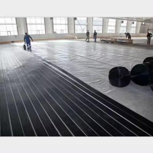
Capillary tube mats system Installation method
Installing a capillary tube mats system involves the following steps:
- Preparation: Start by measuring the total area of the floor or surface where you want to install the capillary tube mats system. Ensure that the surface is clean and free of any debris or obstructions.
- Layout planning: Determine the layout of the capillary tube mats, taking into consideration the specific heating requirements of the area. This may include areas with higher heat loss, such as windows or doors, and areas where more heat is needed, such as living spaces or bathrooms.
- Placement of distribution panels: Install the distribution panels in a convenient location, where they can be easily accessed for maintenance and control. These panels distribute the heated water to the capillary tube mats.
- Securing the capillary tube mats: Lay out the capillary tube mats according to the planned layout, ensuring that the mats are properly spaced and stretched out. Secure the mats to the floor using adhesive or clips, making sure they are firmly in place.
- Connecting the capillary tube mats: Connect the capillary tube mats to the distribution panels, ensuring that each mat is properly connected and labeled. Use suitable fittings, such as elbows or tees, to create a neat and organized piping system.
- Pressure testing: After connecting all the capillary tube mats, perform a pressure test to ensure that there are no leaks in the system. Apply pressure to the system according to the manufacturer’s specifications and check for any signs of leakage.
- Insulation and covering: Once the capillary tube mats system is installed and tested, it is important to insulate the exposed pipes and mats to prevent heat loss. Use insulation materials specifically designed for underfloor heating systems. Cover the mats with a suitable floor covering, such as tiles, laminate, or carpet.
- Controls and commissioning: Install the necessary control system for the capillary tube mats, which may include thermostats, timers, and zone controls. Commission the system to ensure that it is functioning properly and adjust the controls as needed.
- Final checks: Before completing the installation, thoroughly check the entire system for any leaks, ensure that all connections are secure, and verify that each capillary tube mat is receiving the desired flow of heated water.
Additionally, following the recommended installation guidelines from the manufacturer is crucial to avoid voiding any warranties on the product. These guidelines may include specific instructions on surface preparation, adhesive application, temperature and humidity requirements, and other important factors that can affect the longevity and performance of the installation.
Furthermore, working with a qualified professional, such as a flooring contractor or installer, can ensure that the installation is done correctly and in compliance with local building codes. They have the expertise and experience to handle any challenges that may arise during the installation process.
By following the manufacturer’s guidelines and working with a qualified professional, you can mitigate potential risks and ensure a successful and long-lasting installation. This will help you enjoy the benefits of your flooring for years to come.
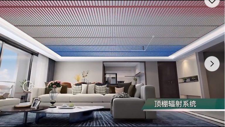
The use of Hydro capillary capillary mats for cooling purposes is a recommended method. These mats can be installed either in the ceiling or in a loosely stretched manner, including under a decorative grid.
By installing the capillary mats in the ceiling, under various finishing materials, efficient cooling can be achieved. This method allows for a uniform and evenly distributed cooling effect throughout the room. The mats absorb the heat and transfer it to the cooling water system, providing a comfortable environment.
Another option is to install the capillary mats in the floor for a “gentle” floor cooling system. However, it is important to note that a ceiling cooling system is generally considered to be more efficient. This is because cold air tends to sink, and when cool air is delivered from the ceiling, it can effectively cool the entire room.
In summary, the installation of Hydro capillary capillary mats either in the ceiling or in the floor provides cooling benefits. However, for optimal efficiency, a ceiling cooling system is recommended.
By maintaining a small temperature difference between the supply and reverse temperatures, the surface temperature of the ceiling can be controlled at around 19°C. To prevent condensation, each control area is equipped with dew point sensors. These sensors monitor the dew point and detect the presence of condensate. If condensation is detected, the flow through the mats is stopped by either closing the control valve or gradually increasing the supply temperature. This ensures that the risk of condensation is minimized and the surface cooling system operates safely.
This combination of radiant cooling ceilings and support ventilation is beneficial as it helps to achieve both sensible and latent cooling loads effectively. By controlling the relative humidity levels through ventilation, occupants can enjoy a comfortable environment without any concerns about high humidity levels or condensation. The radiant cooling ceiling system is responsible for efficiently removing a significant portion of the cooling load, reducing the reliance on the ventilation system.
Reducing the air exchange rate to the minimum required for hygiene purposes also has economic advantages. It allows for the downsizing of ventilation equipment, resulting in cost savings in terms of both equipment size and energy consumption. This combination of radiant cooling ceilings and support ventilation is a practical solution for achieving optimal indoor comfort and energy efficiency in various building types.


Primary and secondary circuit
In a primary circuit, the oxygen that diffuses into the water comes in direct contact with the metal surfaces of the pipe. This can lead to corrosion and the formation of rust.
In a secondary circuit, a barrier is present between the oxygen and the metal surfaces. This barrier can be in the form of a protective layer or a separate pipe that encloses the primary pipe. The barrier prevents direct contact between the oxygen and the metal, reducing the risk of corrosion and rust formation.
The use of a secondary circuit can greatly extend the lifespan of a polypropylene pipe by protecting it from the detrimental effects of oxygen diffusion. It is commonly employed in applications where maintaining the purity and quality of the water is crucial, such as in drinking water systems or pharmaceutical manufacturing.
These separate water circuits in the Hydro capillary system are designed to provide protection against oxygen-induced and microbacterial corrosion. By using stainless steel heat exchangers, the two circuits are kept completely isolated from each other, preventing any contamination or corrosion issues.
The first water circuit is responsible for carrying the heating or cooling medium, such as heated or chilled water. This circuit runs through the stainless steel heat exchangers, ensuring efficient heat transfer between the medium and the capillary tubes.
The second water circuit is dedicated to carrying the treated water that comes into direct contact with the capillary tubes. This circuit is protected against oxygen-induced and microbacterial corrosion by implementing appropriate measures. These measures may include oxygen scavengers, biocides, or other corrosion inhibitors as recommended.
By separating the two water circuits and providing the necessary protection measures, the Hydro capillary system minimizes the risk of corrosion and ensures the long-term integrity and efficiency of the system.
This results in two completely separate circuits which are known as the primary circuit (cold/heat source to heat exchanger) and secondary circuit (from the heat exchanger to the mats). The heat exchanger is part of a compact transfer station in the secondary circuit which consists of the circulation pump and the expansion vessel, among other things.
All components having contact with water in the secondary circuit must be made of corrosion-resistant materials such as plastic, stainless steel, bronze or brass.
Nowadays there are models of heat pumps and gas boilers available which do not contain any elements that can cause corrosion in the system. In such cases the heat exchanger isn’t necessary.
It’s recommended to check the specifications of a particular model of heat pump or gas boiler (including the circulation pump housing before the planning stage of the system is completed.
Water is filled in the secondary circuit only once during the system installation process, and water circulates in a closed circuit.
")
")


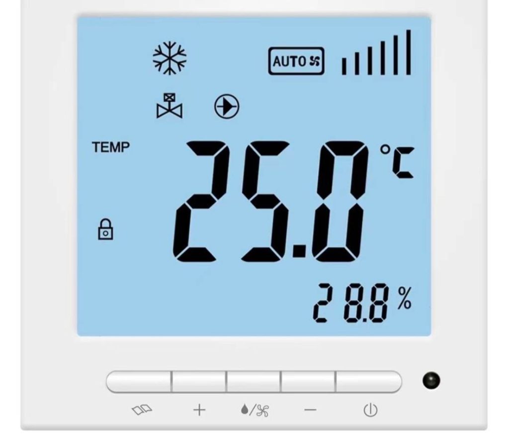
Greata System control concept
As a result of the low water content and the spreading of 2 K or 3 K, the zone control is effected as a two-point control (on/off). As a rule, a constant control of the water flow is not considered practical as the two-point control is effective enough.
Depending on the control signal of the room temperature controller, the electro-thermal actuator on the relevant zone valve either opens or closes. Zone temperature control occurs separately for each zone where the set point can have both centralized and decentralized adjustment. A switch over between heating or cooling operation can also be carried out centrally.
In addition, in case of cooling, each zone is equipped with a dew point sensor. This has only the function of a safety device which either shuts off the zone where there is a danger to reach a dew point – even if the room temperature is above the set point – or it gradually raises the supply temperature according to the relative humidity of the room and/or the enthalpy of the ambient air condition.
You can find actuators, as well as other system control elements, suitable for the Greata Hydro Capillary system in our Product catalog ›
Manifolds for the Hydro Capillary tube system
Supply and return lines of individual zones are connected to manifolds. There are different models available with 2 to 18 outlets.
Important! Connection of max 18 m2 of capillary mats can be planned per each hydraulic circuit.

The connection of the capillary mats to the manifold is made with welded PPR pipes PN10 and fittings of the required diameter.
You can find manifolds suitable for the Greata water Capillary system in our Product catalog ›
Valves for water flow control and hydraulic balancing
When it comes to capillary tube mats, which are specific components of underfloor heating systems, there are specific valves that are commonly used for water flow control and hydraulic balancing. These valves are designed to work with the unique properties of capillary tube mats to ensure optimal performance and energy efficiency. Here are some commonly used valves for capillary tube mat systems:
- Manifold with Flow Meters: The manifold is the central distribution point for the capillary tube mat system. It typically includes flow meters, which allow for visual monitoring of the flow rate in each circuit. This helps to balance the system by ensuring that each circuit receives the appropriate amount of water flow.
- Thermal Actuator Valves: Thermal actuator valves are used to control the flow of water into each circuit of the capillary tube mat. They are typically controlled by room thermostats or other temperature control devices, and operate based on the demand for heating or cooling in each specific area.
- Differential Pressure Control Valve: This valve is used to balance the pressure between the supply and return lines of the capillary tube mat system. It ensures that an equal amount of water is circulated through each circuit, regardless of the length or layout of the capillary tubes.
- Circulation Pump: While not technically a valve, the circulation pump is a crucial component for maintaining proper flow and hydraulic balance in a capillary tube mat system. It helps to ensure that the water is circulated through the capillary tubes and through the manifold at the correct rate.
These valves work together to control and balance the water flow in a capillary tube mat system, providing even and efficient heating or cooling throughout the targeted area. Proper installation and adjustment of these valves is essential for the optimal performance of the system.

Hydraulic module for Greata Capillary tube mats
CE standard hydraulic module consists of some elements as follows:
- adjustable, corrosion-resistant circulation pump (WILO, GRUNDFOS Magna, etc.);
- plastic heat exchanger or stainless steel heat exchanger (if necessary);
- two manometers 0 – 4,0 bar;
- two thermometers 0 – 40°C;
- two ball valves with hose connection;
- shutoff ball valves, with pipe nominal width of main supply and return lines;
- membrane expansion vessel, drinking water design type.
- brass membrane safety valve;
The configuration of the hydraulic module depends on the technical parameters of the selected heat or cold energy source.
- Inlet and outlet connectors: These connectors allow the hydraulic module to be connected to the capillary tube mats in the ground or wall. They ensure a secure and leak-free connection.
- Control valves: The hydraulic module will typically have control valves that regulate the flow of fluid within the capillary tube mats. These valves can be adjusted to control the temperature and flow rate of the fluid.
- Pressure gauges: Pressure gauges are used to monitor the pressure within the hydraulic module and the capillary tube mats. They provide feedback on the system’s performance and help in diagnosing any potential issues.
- Temperature sensors: Temperature sensors are used to measure the temperature of the fluid leaving the hydraulic module and entering the capillary tube mats. They help to control the heating or cooling output of the system.
- Pump: The hydraulic module may include a pump to circulate the fluid through the capillary tube mats. The pump ensures a constant flow rate and pressure, which is essential for efficient operation.
- Safety features: CE standard hydraulic modules will often have built-in safety features such as overheat protection and automatic shutdown in case of system faults or abnormal conditions. These features help to ensure the safety of the system and prevent any damage.
- Mounting brackets: Mounting brackets are used to securely fix the hydraulic module in place. They provide stability and prevent any movement or vibration during operation.
- Electrical control panel: The control panel allows the user to monitor and control various parameters of the hydraulic module. It may include buttons, switches, and indicators for adjusting flow rate, pressure, and temperature.
- Insulation: CE standard hydraulic modules are typically insulated to reduce heat loss and improve energy efficiency. Insulation helps to maintain the desired temperature within the hydraulic module and minimize wastage.
These elements work together to create a CE standard hydraulic module for Greata capillary tube mats. They ensure the proper and efficient functioning of the heating or cooling system, providing comfort and energy savings in buildings.